Choosing a 3-Point Bending Tensile Testing Machine requires more than comparing prices and maximum load ratings. In a working laboratory, small details matter. A poorly aligned fixture can produce uneven stress across a plastic strip or metal specimen. An unstable frame may create vibration during loading. These problems can distort results, even when the software displays precise decimals. This guide presents five practical tips for evaluating machine performance, configuration, and long-term value.
The selection process should begin with your actual testing requirements. Consider specimen dimensions, material behavior, bending span, tensile range, and expected test speed. The load cell must match your routine tests without sacrificing measurement sensitivity. Fixture design also deserves close attention. Smooth supports, accurate spacing, and simple specimen placement can improve repeatability. Calibration records, compatible standards, data export, and technical support are equally important. An experienced supplier should explain these points clearly and provide verifiable specifications, not vague promises. Still, no checklist can predict every laboratory challenge. Operators may discover that a convenient fixture is difficult to clean, or that advanced software is rarely used. That is why trial demonstrations, reference samples, and honest discussion with technicians remain valuable. A reliable 3-Point Bending Tensile Testing Machine should support consistent results, practical operation, and future testing needs. Choose carefully. Reconsider assumptions.
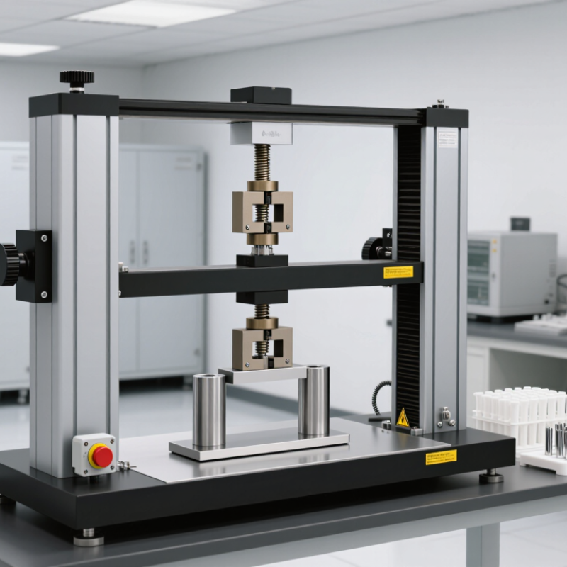
Choosing a 3 Point Bending Tensile Testing Machine starts with defining the material and test requirements. The machine must match the specimen’s composition, size, stiffness, and expected failure behavior. Plastics, metals, composites, and rubber require different force ranges and fixture designs. A machine that is too powerful may reduce measurement sensitivity. One that is too weak may stop before failure.
Clarify whether the test is flexural, tensile, or both. Three-point bending usually measures flexural strength, modulus, and deflection rather than direct tensile strength. Select a recognized method, such as ASTM D790 or ISO 178, when applicable. Check the required span length, loading rate, specimen dimensions, and deformation limits. These details influence the frame design, load cell, and displacement resolution. Small errors matter.
Think about the working environment. Temperature control may be essential for polymers or moisture-sensitive materials. Confirm whether the machine can record force and displacement continuously. Data should remain traceable, repeatable, and easy to review. In practical testing, fixture alignment often causes unexpected variation. A perfect-looking specimen cannot correct poor alignment. I have also seen operators choose a load cell based only on maximum force, then lose accuracy at low loads. That choice deserves another look. Define the smallest meaningful force before selecting the sensor. Check calibration intervals, software reporting, operator safety, and maintenance access before approving the final configuration.
5 Tips for Choosing a 3 Point Bending Tensile Testing Machine
Select the Correct Bending and Tensile Test Configuration
A suitable machine must support two different loading arrangements. Three-point bending needs two stable supports and a centered loading nose. Tensile testing needs aligned grips, a defined gauge length, and controlled separation. Do not assume one fixture can perform both tasks well. Check the working space before purchase. A short frame may limit larger specimens.
Match the load cell to the material and specimen size. The expected force should sit comfortably within the sensor’s useful range, not near its maximum. Select adjustable support spans for bending tests. Their scale should be clear and easy to lock. For tensile work, inspect grip surfaces and clamping pressure. Slipping leaves misleading results. It happens more often than expected.
Control matters.
Crosshead speed should follow the applicable test method and material behavior. A stiff plastic and a soft rubber sample may need very different settings. Confirm that force, displacement, and strain can be recorded together. An extensometer may improve tensile accuracy, while bending often relies on displacement measurement. Ask about calibration procedures, software records, and emergency stops. In routine laboratory work, alignment checks save more samples than sophisticated features. Still, I would not ignore frame stiffness. A machine can look precise while its fixture flexes under load. Test a reference specimen periodically, and question results that change without a clear material reason.
| Tip | Selection Dimension | Recommended Configuration | Relevant Data or Requirement | Why It Matters |
|---|---|---|---|---|
| 1 | Determine the required force capacity | Select a load cell and frame capacity above the maximum expected test force. | Use the anticipated peak force plus a safety margin. Common laboratory frame capacities include 1 kN, 5 kN, 10 kN, 50 kN, and 100 kN, depending on the specimen and material. | The machine should complete the test without overload while maintaining suitable force resolution. A capacity that is unnecessarily high can reduce measurement sensitivity for small loads. |
| 2 | Match the fixture to the test method | Use a three-point bending fixture with two lower supports and one centrally positioned loading nose. | The support span should be adjustable to suit the specimen geometry and applicable standard. The loading nose and supports should be aligned, hardened, and appropriate for the material. | Fixture geometry directly affects bending moment, stress distribution, deflection, and repeatability. Incorrect span or alignment can produce misleading flexural-strength results. |
| 3 | Check specimen size and span compatibility | Choose a machine with adequate test-space height, width, throat depth, and span-adjustment range. | For rectangular specimens, calculate the span-to-depth ratio according to the selected method. ASTM D790 commonly uses a span-to-depth ratio of 16:1 for many plastic flexural tests, while other standards may specify different ratios. | A suitable span helps promote the intended flexural failure mode and prevents fixture interference, excessive shear effects, or insufficient deflection travel. |
| 4 | Select appropriate deformation measurement | Use crosshead displacement for general screening and a deflectometer or extensometer when accurate modulus or strain data are required. | Crosshead displacement includes machine and fixture compliance. A separate displacement sensor measures specimen response more directly. Sensor travel and range must cover the expected deflection. | Accurate deformation measurement is essential for flexural modulus, yield behavior, and comparison between materials. The selected sensor should not restrict the specimen movement. |
| 5 | Verify software, speed, and compliance needs | Choose software that supports force, displacement, stress, strain, modulus, and failure-point calculations. | Test speed must be programmable in the units required by the applicable standard, such as mm/min. The system should record calibrated force and displacement data and export results in common formats such as CSV. | Controlled speed and traceable data processing improve repeatability. The machine should also support calibration records, test-result storage, and reporting requirements for the laboratory. |
Note: Final machine capacity, fixture dimensions, test speed, specimen geometry, and calculation method should be selected according to the applicable material standard and the expected test range.
5 Tips for Choosing a 3 Point Bending Tensile Testing Machine
Tip 1: Check the load capacity against your strongest expected specimen. A machine rated too low may overload quickly. One rated far too high can reduce sensitivity during light tests. Leave a practical safety margin, but avoid paying for unused force.
Tip 2: Examine accuracy across the working range, not only the headline specification. Ask for calibration records, verification methods, and repeatability data. In daily testing, small force errors can change a borderline result. I have seen operators trust a display without checking the load cell. That is risky. Calibration matters.
Tip 3: Match the measurement range to the specimen size and deformation. Confirm the available span, crosshead travel, displacement resolution, and fixture adjustment. A wide range sounds useful, yet poor resolution at small deflections can hide important material behavior. Check the details.
Tip 4: Inspect how the machine controls speed and records force. Stable movement helps produce comparable results between operators. The software should capture force and displacement continuously, with exportable test data. Manual notes are convenient, but they invite missed peaks and timing mistakes.
Tip 5: Consider alignment and support quality. The loading nose and supports must contact the specimen evenly. Uneven contact may create twisting, premature cracking, or misleading strength values. Request a demonstration with a specimen similar to yours. Specifications alone do not reveal everything.
One point deserves reflection: “accuracy” is not only a machine feature. It also depends on specimen preparation, fixture wear, temperature, and operator technique. A well-built tester cannot correct a warped sample. Verify the complete testing process before accepting its results.
The machine should support force, displacement, and angle verification under recognized procedures. ASTM E4 covers force verification, while ISO/IEC 17025 emphasizes traceable calibration results. Ask for sample certificates, uncertainty values, and recommended intervals. A neat certificate is not enough.
Include grips, sensors, software updates, annual calibration, energy use, and technician travel. The U.S. Department of Energy’s Operations & Maintenance Best Practices Guide reports that predictive maintenance can reduce costs by up to 30% compared with reactive maintenance. That figure is not guaranteed for every laboratory. Still, it shows why maintenance planning matters.
Request a written response-time target, spare-part availability, remote diagnostics, and training details. A machine waiting three weeks for a simple sensor can disrupt scheduled testing and delay customer reports.
Look for labor coverage, calibration exclusions, software support, and emergency fees.
The system should export raw results, preserve audit trails, and protect method settings from accidental changes. NIST guidance consistently links reliable measurement to documented traceability and uncertainty evaluation. Ask whether local technicians are qualified. This is often overlooked. A cheaper machine may become costly when operators improvise repairs or repeat failed tests. Before deciding, compare three years of ownership costs using your actual test volume, not the supplier’s ideal workload.
Stay in touch with the latest National Luna Products and News!